Mobile CNG supply
The cascade & cart: your gas supply on wheels
The problem it solves
A fixed cascade strands your gas supply
A converted generator needs a supply of compressed natural gas. The conventional approach is a bank of high-pressure cylinders — a cascade — welded into a fixed rack and plumbed to the engine. That works perfectly well until the cylinders run low.
At that point a fixed rack becomes a problem. Traditional cascade frames are tall, top-heavy, and have no transport fittings, so moving one means a forklift or a crane, and a specialist to break and remake the gas connections. In practice that means either a tanker delivery contract or downtime.
Our approach: design the cascade from the outset so one or two people can roll it off, load it on a cart, and take it to the station themselves — with a single coupling to disconnect.
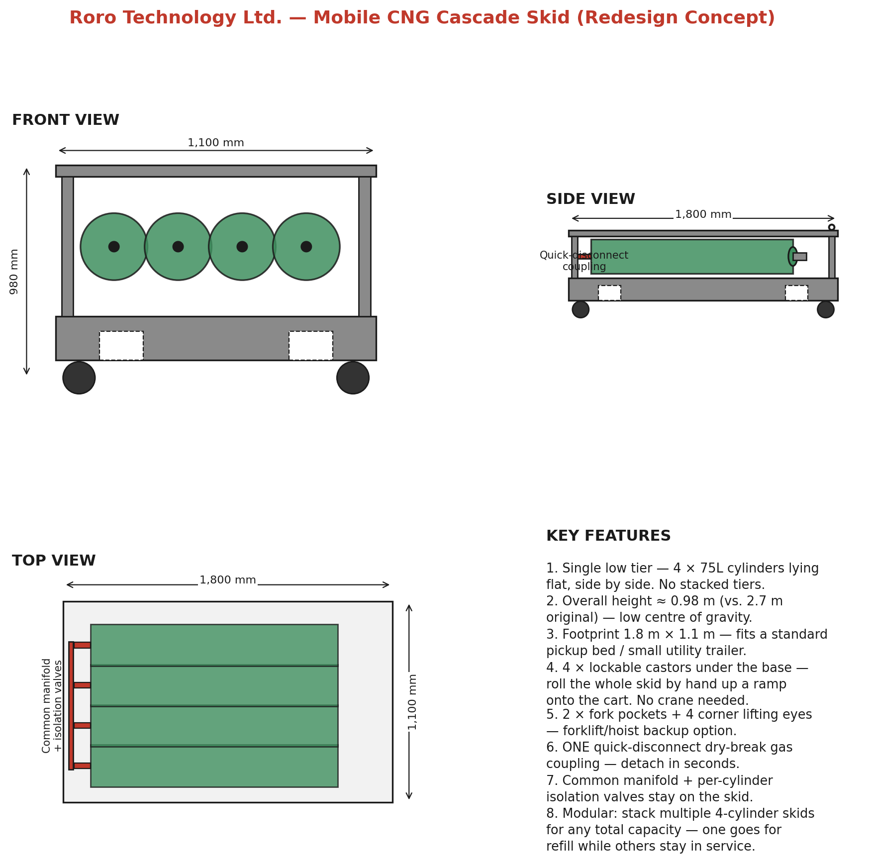
Mobile CNG cascade skid — front, side and top views with key features
The design
What we changed, and why
| Design aspect | Conventional fixed rack | Roro mobile skid |
|---|---|---|
| Cylinder arrangement | Two stacked tiers, up to 16 cylinders | Single low tier of 4 cylinders lying flat, side by side |
| Overall height | ≈2,700 mm — tall and top-heavy | ≈980 mm — low centre of gravity |
| Footprint | ≈2,800 mm wide | 1,800 × 1,100 mm — fits a standard pickup bed or small utility trailer |
| Moving it | Forklift or crane required; no transport fittings | Four lockable castors — rolls by hand up a ramp onto the cart |
| Gas connection | Multiple hard-plumbed connections to break and remake | One quick-disconnect dry-break coupling, released in seconds |
| Capacity growth | Replace the whole rack | Add cylinders, or run multiple skids so one refills while others stay in service |
In practice
A refill trip, start to finish
- 1
Close the master valve
One valve on the cascade manifold stops all gas flow to the generators. The generating sets can continue running on 100% diesel throughout the trip if you need them.
- 2
Release the single quick-disconnect coupling
The dry-break coupling that links the cascade to the generators' gas line detaches by hand and self-seals on both sides. No tools, no gas fitter, nothing vented.
- 3
Roll the cascade onto the cart
Unlock the castors and roll the skid up the ramp onto the cart. Its low centre of gravity is what makes this safe to do by hand rather than by machine.
- 4
Strap down and lock the castors
Tie-down straps secure the skid to the cart and the castors are locked, so nothing shifts in transit.
- 5
Tow to the station with any vehicle
The cart has tyres and standard fittings, so it attaches to whichever truck, pickup or vehicle is available that day — it is not tied to one dedicated vehicle.
- 6
Refill all cylinders at the station
Filling is through the same single coupling in reverse. Each cylinder has its own isolation valve, so any one can be isolated if needed.
- 7
Return, reconnect, re-open
Drive back, roll the skid off the cart, reconnect the coupling, and re-open the master valve. Your generators are back on gas.
The key point: only the cascade ever leaves site. The dual-fuel kit, the gas train on the engine side, the controller and all the safety systems stay exactly where they are and are never disturbed by a refuelling trip.
Engineering detail
Built for the job
Low single tier
Four 75-litre cylinders lie flat, side by side, in one tier. No stacking means a low centre of gravity and no need to lift a cylinder above waist height.
Four lockable castors
Two fixed and two swivel, heavy-duty rated against the loaded weight of roughly 440 kg. Locked in transit and while connected on site.
Fork pockets & lifting eyes
Two fork pockets in the base and four corner lifting eyes, so the skid can still be handled by forklift or hoist where machinery is available.
One dry-break coupling
A single self-sealing quick-disconnect per skid. It cannot be left leaking when detached, and there is only one connection to get right.
Manifold stays on the skid
The common manifold, per-cylinder isolation valves, master shut-off and pressure relief valve all travel with the cascade — nothing is dismantled to move it.
Modular by design
Multiple skids can be run in parallel for greater total capacity, so one can go to the station while the others stay in service and your generators never wait for gas.
Specifications
Typical 4-cylinder mobile cascade
| Item | Specification |
|---|---|
| Cylinder capacity | 4 × 75-litre NGV-rated CNG cylinders |
| Footprint | ≈1,800 mm (L) × 1,100 mm (W) |
| Overall height | ≈980 mm |
| Loaded weight | ≈440 kg (4 full cylinders + skid frame) |
| Mobility — primary | 4 × heavy-duty lockable castors (2 fixed, 2 swivel) |
| Mobility — backup | 2 × fork pockets, 4 × corner lifting eyes |
| Gas connection | 1 × quick-disconnect self-sealing (dry-break) coupling |
| On-skid plumbing | Common manifold rail, isolation valve per cylinder, master shut-off, pressure relief valve |
| Frame | Welded steel channel/angle, powder-coated, with perimeter bumper at cylinder height |
| Cart | Wheeled cart with tyres; attaches to any suitable vehicle or truck |
Safety
How the system is kept safe
- Per-cylinder isolation. Every cylinder has its own valve on the manifold, so any single cylinder can be isolated without shutting down the bank.
- Master shut-off. One valve stops all gas flow to the generators — the first action in any refill or emergency procedure.
- Pressure relief. A relief valve protects the manifold against over-pressure.
- Self-sealing coupling. The dry-break design means the connection cannot be left venting when detached.
- NGV-rated throughout. Cylinders, valves and fittings are rated for natural-gas-vehicle service pressures.
- Strapped, not welded. Cylinders are clamped and strapped into the frame so they can be individually removed for periodic inspection and recertification.
- Transport compliance. We advise on the local regulations that apply to carrying compressed gas cylinders by road, and the safe route off and back onto your site.
Not sure how many cylinders you need?
Cylinder count follows from your generator size, load and how often you are willing to make a refill trip. Tell us your setup and we will size the cascade for you.
Or email sales@rorotechnologies.com